
Using an external sensing resistor when the power supply’s current monitor does not provide enough resolution
A high-voltage power supply’s built-in current monitor is usually the simplest way to observe load current. In many research systems, however, the current of interest is below the monitor’s useful measurement range—or the experiment requires a more sensitive, branch-specific measurement.
One practical solution is to place a carefully selected sensing resistor in the low-potential return path and measure the voltage across it with a digital multimeter or data logger. Ohm’s law then converts that voltage into current. When the load return can be isolated from earth, the resistor can be installed between the load and ground. When the load is inseparable from a grounded metal structure, a battery-powered LabMate can instead be operated as an intentionally floating supply, with the resistor placed between the supply’s central ground point and earth.
These two arrangements solve different grounding problems. Both require deliberate control of every return path and appropriate transient protection.
Safety boundary: This article describes measurement architecture, not energized construction or troubleshooting. High-voltage equipment can retain hazardous energy after shutdown. Make wiring changes only with the output set to zero, power removed, stored energy discharged, and the absence of hazardous voltage independently verified. Any custom sensing circuit should be reviewed by a qualified person and installed inside a suitable enclosure.
Institutional electrical-safety guidance should govern the work in addition to the equipment manual and local procedures. [2, 3]
Begin with the LabMate current monitor
LabMate is a regulated high-voltage power supply with a front-panel current indication. For normal setup, process monitoring, current-limit awareness, and fault detection, this built-in measurement should be the starting point. Analog Remote Control models also provide a current-monitor signal that can be used for logging when connected and scaled according to the documentation for the exact model.
An external sensor becomes useful when:
- The expected current is smaller than the useful resolution or measurement range of the built-in monitor.
- Greater measurement sensitivity or accuracy is needed over a narrow current range.
- The current through one load branch must be distinguished from other leakage or return currents.
- The experiment needs a voltage signal that is conveniently scaled for a particular meter or data logger.
An external reading does not replace the LabMate monitor. The two measurements are complementary: the LabMate shows the behavior of the supply as a whole, while a properly located sensing resistor can provide a closer view of the selected current path.
Use the maximum possible output current—not only the expected reading—when sizing the sensing circuit. LabMate 10 models can supply up to 2 mA. LabMate 30 models are specified for up to 0.4 mA at 30 kV and can supply up to 0.5 mA at lower output voltages. Confirm the limits and monitor scaling for the exact model and configuration.
The basic sensing-resistor method
Place a sensing resistor, Rsense, in the return path and measure the voltage across it, Vsense. The current is:
I = Vsense / Rsense
For example, the 1 kOhm sensing resistor shown in the accompanying schematics produces 1 V when 1 mA flows through it. If a much smaller current must be resolved, a larger resistor can produce a more useful measurement voltage. A 1 MOhm resistor, for example, produces 1 V at 1 uA.
Higher resistance is not automatically better. The resistor also creates a voltage drop—often called burden voltage—in the return path. Its value must therefore be chosen from the expected current range and the highest credible current, not from the nominal current alone:
Vsense(max) = Imax x Rsense
Pmax = Imax^2 x Rsense = Vsense(max)^2 / Rsense
The design goal is a signal large enough to measure accurately without creating an excessive voltage rise, disturbing the experiment, or exceeding any component or instrument rating.
Selecting the resistor and measuring instrument
Consider all of the following:
- Resistance and tolerance: Choose a value that gives useful resolution across the expected current range. Use the resistor’s measured value if the uncertainty matters.
- Maximum current: Calculate the sensing voltage and dissipation at the highest current that can actually occur, including the selected supply current limit and credible abnormal conditions.
- Power, working-voltage, and pulse ratings: A resistor can remain below its steady-state wattage rating and still be unsuitable for the voltage across it or for discharge energy during a transient.
- Temperature coefficient: Self-heating and ambient changes can shift resistance and measurement accuracy.
- Meter input impedance: The meter or logger appears in parallel with the sensing resistor. Its input resistance should be high enough that it does not materially change the effective resistance.
- Resolution, accuracy, and noise: Select the resistor and measurement range together. At very low currents, contamination, humidity, cable motion, and electrical interference may dominate the result.
Low-current measurements become increasingly sensitive to insulation quality, surface leakage, shielding, guarding, and instrument input characteristics as the target current decreases. [1]
Method 1: Place the sensing resistor between the load and ground
When the load’s low-potential terminal can be separated from earth, the most direct arrangement is to place the sensing resistor between that terminal and the system’s designated grounding point. All intended load current then passes through the resistor before returning to the supply.
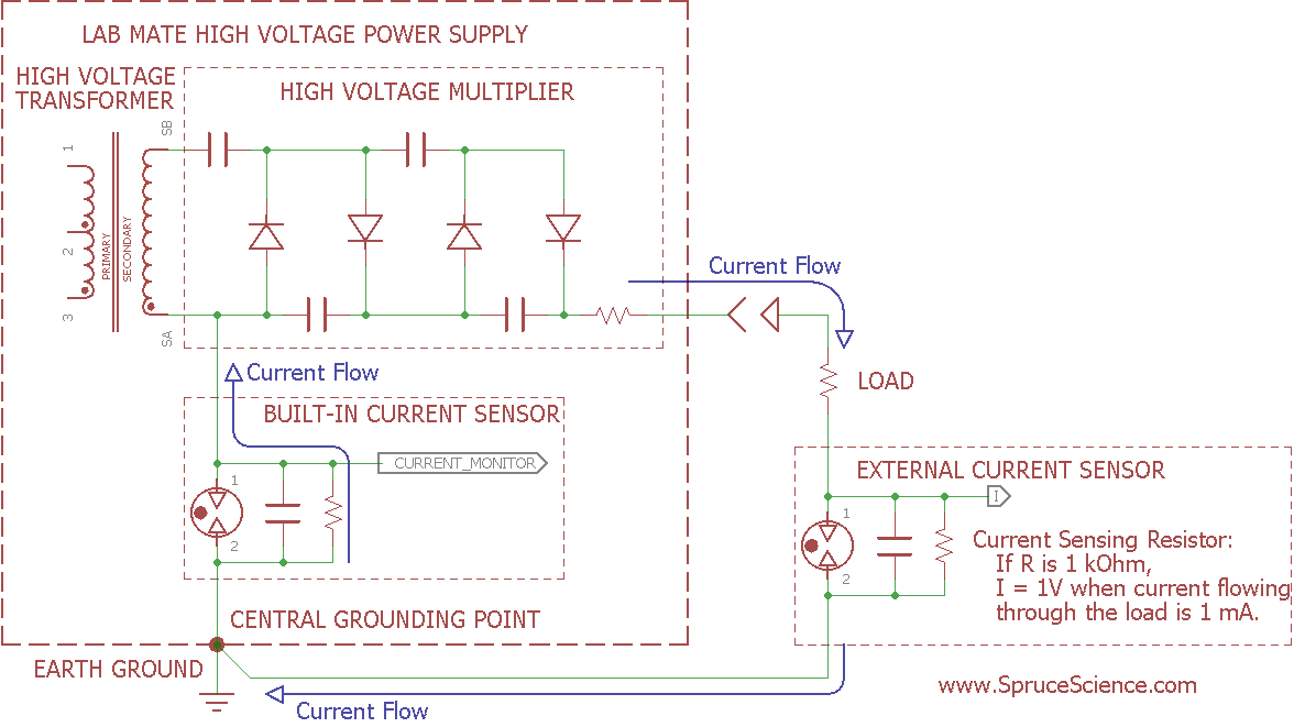
Figure 1. A low-side external sensor measures a defined load-return branch while the LabMate remains earth-referenced.
In this topology:
- High-voltage output current passes through the load.
- The current flows through the external sensing resistor.
- The resistor develops a low-voltage signal referenced near earth ground.
- A digital voltmeter or data logger measures that signal.
- The current returns through the normal grounded return to the power supply.
This method is especially useful when a microampere-level signal would be difficult to resolve with a monitor designed to cover the power supply’s full current range. It can also measure one selected collector, electrode, or load branch, provided no parallel conductor bypasses the resistor.
The load side of the resistor is not exactly at earth potential; it rises by Vsense. Keep this voltage within the limits of the apparatus and of anything connected to that node. A frame, shield, cable, or instrument ground connected on both sides of the resistor will bypass some current and invalidate the measurement.
Protect the measurement input from transients
An arc or rapid discharge can place a short, energetic pulse on a low-side sensing circuit. The schematic includes a gas discharge tube across the sensing resistor to divert a sufficiently large voltage spike and help protect the connected meter or logger. The sensing resistor, discharge tube, and any filtering or secondary clamping should be chosen as a coordinated protection network.
A gas discharge tube is not a guarantee that an arbitrary instrument is protected. Its firing voltage, response behavior, capacitance, surge rating, and the instrument’s maximum input rating all matter. The layout should keep the transient path short and away from accessible conductors. The protection design should be reviewed against the energy stored in the supply, output cable, load, and any added capacitance.
Method 2: Measure below a battery-powered floating LabMate
Sometimes the load’s return is mechanically and electrically tied to earth—for example, a collector built into a grounded metal chamber, frame, or worktable. In that situation, inserting a resistor between the load and earth may be impractical or may leave multiple parallel return paths.
A different option is available when the LabMate is powered from a suitable battery pack and the entire supply is intentionally isolated from earth. The sensing resistor is placed between the LabMate’s central ground or chassis reference and earth ground. The load may remain directly connected to its grounded structure, while the complete output current returns to the supply through the sensing resistor.
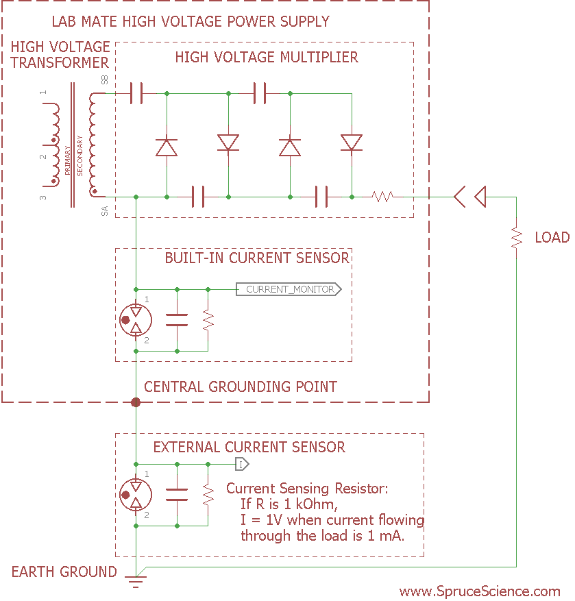
Figure 2. With the load fixed at earth potential, the battery-powered LabMate floats above earth only by the voltage developed across the sensing resistor.
The whole supply is displaced from earth by the sensing voltage:
Vchassis-to-earth = I x Rsense
For the intended arrangement, the resistor is selected so the worst-case chassis-to-earth bias remains small—on the order of 10 V or less—while still producing a useful measurement signal. Because the required isolation voltage is low, a battery-powered LabMate can make this topology practical when the load itself cannot be floated.
This arrangement is best understood as moving the external sensor from the load return to the supply return. The sensing resistor may measure all current returning to the floating supply, including unintended leakage through accessories or interfaces. That makes isolation discipline essential.
Important distinction: Intentional battery-powered operation is not the same as removing protective earth from an AC-powered instrument. Do not defeat the protective-earth connection of an AC-powered LabMate, bench meter, oscilloscope, computer, or data-acquisition system. Use the floating arrangement only where battery operation and the permitted chassis-to-earth bias are supported by the applicable equipment instructions.
Keep every connection within the floating system
Before using the floating-supply method, account for every conductive connection to the LabMate. A grounded USB cable, analog-control source, oscilloscope lead, data-logger common, enclosure contact, cable shield, or charging connection can silently reconnect the chassis to earth and bypass the sensing resistor.
Practical requirements include:
- Operate the LabMate from an approved battery source; do not charge the battery during the measurement unless the charging system is specifically designed and rated for this isolation scheme.
- Keep control and monitor interfaces isolated, or use self-contained battery-powered instruments whose common-mode and input ratings are suitable.
- Insulate and enclose the chassis and sensing circuit for the maximum calculated bias and credible transients.
- Limit the chassis-to-earth voltage under both normal operation and the maximum selected output-current condition.
- Verify with the system de-energized that the sensing resistor is the only intended connection between the floating supply reference and earth.
If those conditions cannot be established confidently, do not use the floating topology. Redesign the load return, use an appropriately isolated current transducer, or consult a qualified high-voltage engineer.
Comparing the two external arrangements
| Arrangement | Use it when | What rises above earth | Main concern |
|---|---|---|---|
| Sensing resistor between load and ground | The load return can be isolated and routed through one resistor | Load return by Vsense |
Parallel grounding paths can bypass the sensor |
| Sensing resistor between a battery-powered LabMate and earth | The load is fixed to a grounded chamber, frame, or table | Entire LabMate chassis/reference by Vsense |
Any grounded accessory can defeat the isolation |
Use the first arrangement whenever it fits the apparatus cleanly. The second is a useful alternative for an earth-bonded load, but it requires a complete review of the supply’s power, control, monitoring, enclosure, and accessory connections.
A practical setup sequence
- Draw the complete current loop. Include the LabMate, load, return conductor, protective-earth bonds, frame, shields, control cables, and measurement equipment.
- Choose the topology. Use a low-side load-return sensor if that return can be isolated. Consider the battery-powered floating-supply method only when the load must remain earth-bonded.
- Define the range. Establish the lowest current to resolve and the highest current that can occur with the selected LabMate current limit.
- Calculate the resistor. Confirm signal level, burden voltage, dissipation, working voltage, and fault or pulse stress.
- Design transient protection. Include an appropriately selected gas discharge tube and any additional protection required by the measurement input and stored system energy.
- Inspect for bypass paths. Check chassis bonds, cable shields, grounded instruments, communications cables, and mechanical contacts.
- Install only while de-energized. Discharge the system and verify absence of voltage before touching conductors.
- Commission conservatively. Start at zero, select a low current limit, increase voltage gradually, and compare the external reading with the LabMate monitor.
- Document the configuration. Record the measured resistor value, meter range, conversion factor, current limit, grounding arrangement, and protection components.
Interpreting a disagreement with the LabMate reading
The two readings need not be identical in every setup. Check whether they measure the same current path and whether they use the same averaging or bandwidth. Differences may result from:
- Leakage or corona current that returns through another path.
- A grounded connection bypassing the external resistor.
- Meter loading or an incorrect resistor value.
- Transient charging current during a voltage ramp.
- Noise, resolution, calibration, or timing differences.
- In the floating arrangement, another earth connection to the supply chassis.
If the discrepancy is unexpected, return the voltage command to zero and investigate while the system is de-energized. Do not change grounding or sensing connections on an energized apparatus.
The central idea
The LabMate current monitor is the right tool for routine operation, but its full-range measurement may not resolve every low-current experiment. A sensing resistor converts a selected current into a convenient low-voltage signal and can improve sensitivity or accuracy when it is placed in a carefully controlled return path.
Use a resistor between the load and ground when the load return can be isolated. When an earth-bonded metal load makes that impossible, a battery-powered LabMate can support an alternative arrangement in which the supply floats only by the small sensing voltage. In either case, reliable results depend on resistor selection, transient protection, and a single, clearly understood current-return path.
For related setup guidance, see High-Voltage System Grounding, High-Voltage Power Supply Grounding, Why You Need a Dedicated High-Voltage Probe, and High-Voltage Safety Fundamentals.
References
- Keithley Instruments, Low Current Measurements, application note. https://download.tek.com/document/LowCurtMsmntsAppNote.pdf
- U.S. Department of Energy, DOE Handbook: Electrical Safety. https://www.energy.gov/sites/default/files/2026-05/DOE-HDBK-1092-98.pdf
- Occupational Safety and Health Administration, “Electrical—Overview.” https://www.osha.gov/electrical