Electrospinning Process
Electrospinning of Polyvinylpyrrolidone (PVP)
Demonstration Notes
Electrospinning Process Table of Contents
Introduction to Electrospinning Process
Electrospinning is the method of using a high voltage power supply to produce ultra small diameter fibers. Electrospinning process can be used to produce nanofibers from many synthetic and natural polymers. Some of the attractive properties of the electrospun nanofibers are the small diameter, high porosity and high surface-to-volume ratio. In this demonstration, you will see electrospinning of polyvinylpyrrolidone (PVP). Our hope is to illustrate to you the value of electrospinning machine from Spruce Science for research and development.
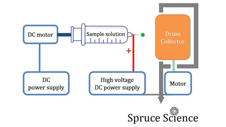
In the electrospinning process, the polymer that you want to make nanofibers are mixed with a solvent and the solution is loaded inside the syringe. Syringe pump flow rate is adjusted to desired flow rate and high voltage is applied to the liquid solution to create a charged jet of polymer solution. When this jet travels in air, the solvent evaporates and leaves behind a charged fiber. Because of the intense electric field that exists between the needle tip and rotating collector, the fibers are electrostatically elongated and collected on the metal sheet. The electrospinning process is simple but produces amazing results.
After reading through this electrospinning process documentation notes, you will see the construction of the electrospinning machine that is powered by Lab Mate high voltage power supply. You will also see the syringe pump and drum collector assembly that is compact but effective. When combined together to form the electrospinning machine, you can explore nanofibers fabrication process.
Electrospinning Apparatus
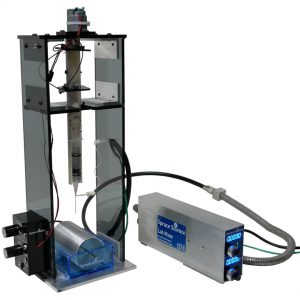
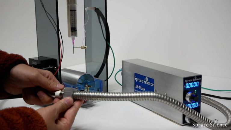
The apparatus used in the electrospinning process is shown below. The hardware consists of the syringe pump, benchtop high voltage power supply, and collector assembly.
The syringe pump is the vessel that holds and deliver the polyvinylpyrrolidone (PVP) solution. This is the sample holder for the electrospinning process. The syringe pump is oriented in the vertical direction and a DC motor slowly pushes the polymer solution through the needle.
The primary driving force behind the electrospinning process is the intense electric field. LabMate is a benchtop high voltage power supply used in this electrospinning process to generate the intense electric field between the sample and grounded collector assembly. This particular high voltage power supply is compact and great for this type of application since the front panel provide easy control over the high voltage output. During the experiment, high voltage in the range of +2kV to +10kV was applied to the liquid sample to make small fibers that are stretched electrostatically.
Electrospun nanofibers that are fabricated are then collected on the drum collector assembly. The drum collector is electrically grounded and electrically charged fibers are attracted to the drum collector. It can be rotated while the electrospun nanofibers are collected.
Each of the sub-assembly and how they function in the electrospinning process will be covered in the sections that follow. After the basics of operation is presented, the results from PVP electrospinning will be presented. Video presentation for the electrospinning process can also be seen on the bottom of the page.
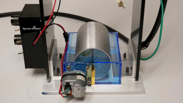
Drum Collector Sub-Assembly
The fibers that are produced in the electrospinning process are deposited on the collector assembly. This electrospinning machine utilize a drum collector that rotates and the speed is adjustable. The collector itself has an important effect on the arrangement of the nanofibers that are produced by the machine. Because of the rotation, the gathered fibers are aligned over a larger area.
The collector is electrically grounded during the electrospinning process. This is important because the potential gradient that exists steer the electrically charged fibers.
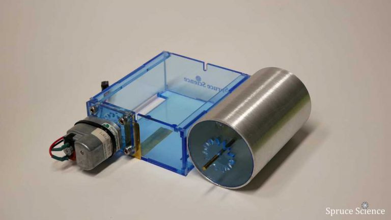
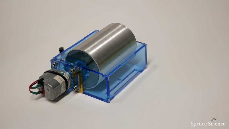
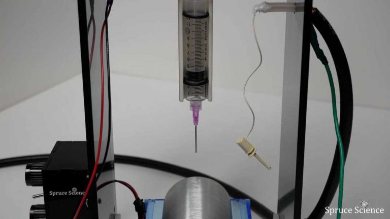
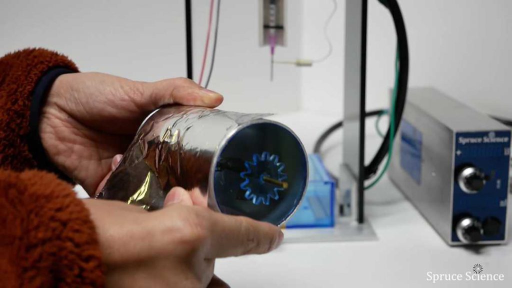
The drum collector sub-assembly can be seen below and the rotation is driven by a DC motor. The drum collector is detachable from the frame and it has spur gears attached on both sides. The drum collector material is Aluminum and the outer diameter is 2.5″.
Collector preparation steps for electrospinning:
- To install the drum collector, align the gears and insert it gently in place.
- Place the collector assembly on top of the aluminum base.
- Connect the DC motor to the controller.
- Plugin 12V and provide power to the Control Panel.
- Turn-on the collector motor.
- The collector rotation speed can be adjusted by turning the dial on the Control Panel. Collector rotation speed is an important tuning parameter for the electrospinning process.
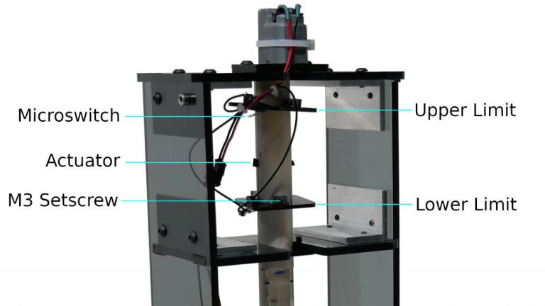
Syringe Pump Sub-Assembly
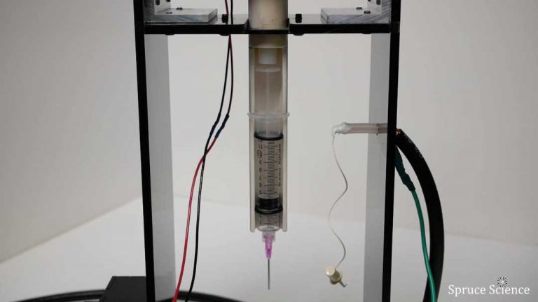
In the electrospinning process, the sample is held inside the syringe pump sub-assembly. The syringe pump is a small pump and it is used to gradually deliver a small amounts of PVP solution for electrospinning. The syringe pump is integrated into the electrospinning tower and it stands erect in the vertical direction. The syringe itself is removable from the frame and syringe driver.
The syringe pump housing is constructed from an insulating plastic tubing and this provide electrical insulation so that high voltage can be applied directly to the needle and sample solution.
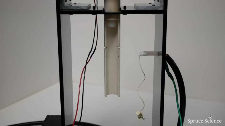
The syringe pump can be seen in the pictures shown below and the following steps illustrate the syringe pump usage during the electrospinning process.
- On the Control panel, push the switch upward to “Reverse” and turn-on the Taylor Cone motor switch. The pump motor will rotate at maximum speed when traveling in the up direction.
- After the highest position is reached, carefully remove the syringe from the white tube housing.
- When you are ready to run experiments, fill the syringe with liquid sample. For alignment purposes, install two o-rings as shown. This particular syringe size is 10 cc.
- Insert the plunger end of the syringe into the white tube housing. Then lock the syringe by placing the hand tab into the slot.
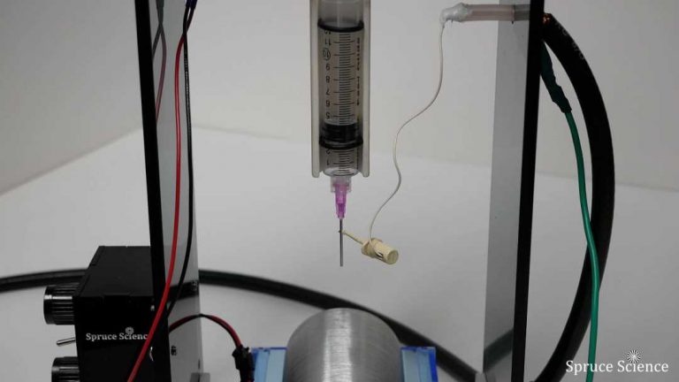
- Set the pump direction to “Dispense” and turn-on the pump. When the pusher inside the white tube is engaged with the syringe plunger, liquid droplets will form at the tip of the needle.
- Dispense speed can be adjusted using the potentiometer located on the Control panel.
- Connect the HV clip to needle.
- WARNING! Make sure the high voltage power supply is OFF before touching the clip.
Benchtop High Voltage Power Supply
It is important to note that having a reliable high voltage power supply is absolutely critical for electrospinning since the intense electric field is the primary driving force behind the electrospinning process.
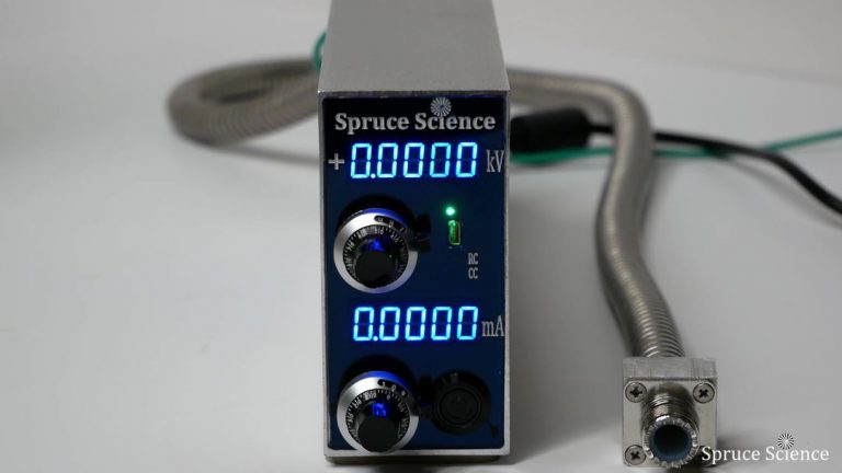
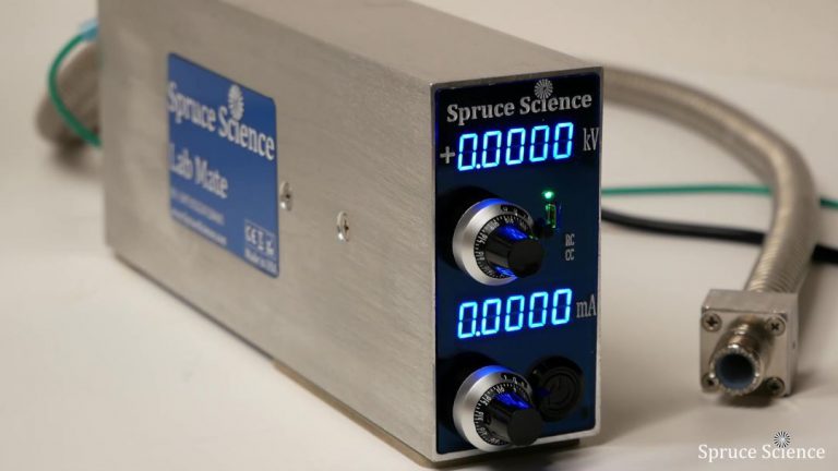
LabMate is the high voltage power supply used in this experiment and it can be seen here. LabMate is an adjustable high voltage switch mode power supply. It is compact, lightweight, and versatile. This compact high voltage power supply can produce 10kV at 2mA.
The compact form factor is great for usage in space-constrained systems since even the simplest experiments end up occupying a lot of space. It is also very convenient that the precision high voltage power supply is highly integrated because it simplifies the setup process. The only thing required from the user to get started is to plug-in.
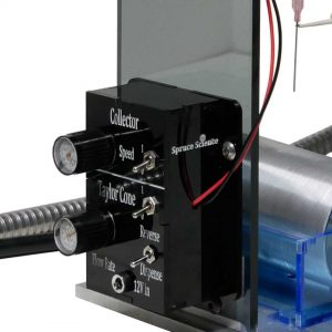
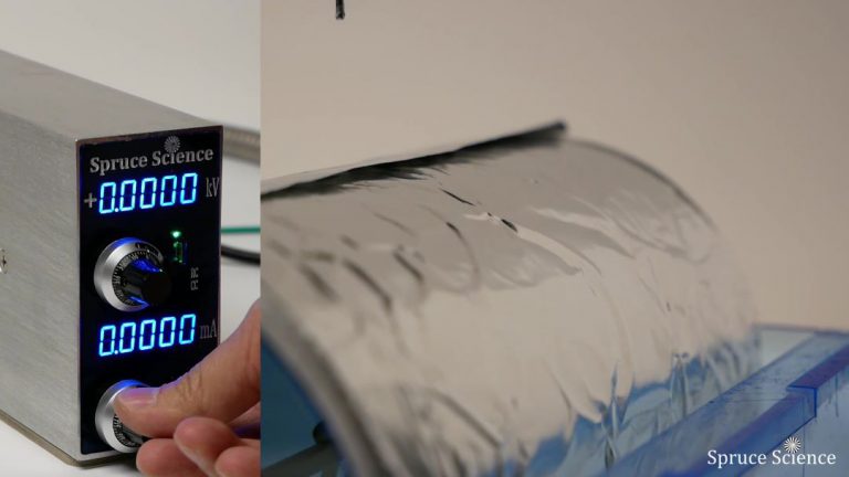
Your front panel control for the generator are as follows: voltage displayed in 5 digits, voltage adjustment dial with turn counting indicator, remote control receptacle, indicator light when the unit is under remote control, indicator light when the unit is in constant current mode, current display, current adjustment dial, and high voltage on/off switch.
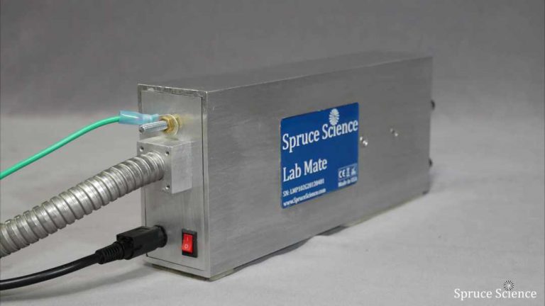
On the back of the generator, you will find M5 threaded stud for grounding, main power on/off switch, DC input connector, HV Output connector.
In order to complete the setup, high voltage connection to the Taylor Cone tower must be made. The following steps illustrate the preparation necessary to get the high voltage power supply operational for the electrospinning process.
- WARNING! It is important to note that proper grounding is very important.
- Make a secure ground connection between the high voltage power supply and earth ground.
- Make the 24V connection.
- Connect the high voltage power supply to Taylor Cone tower.
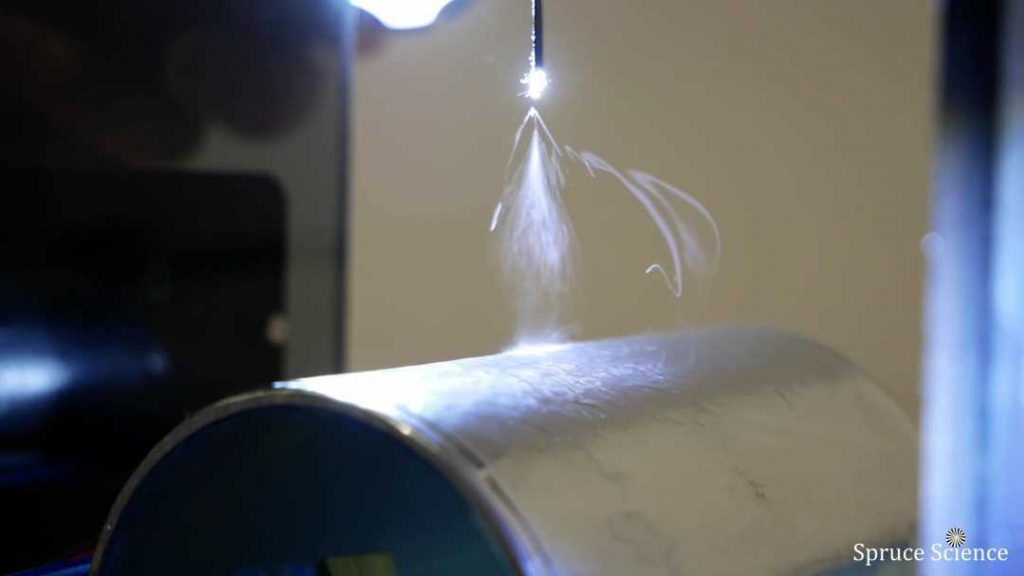
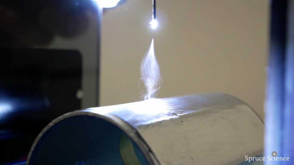
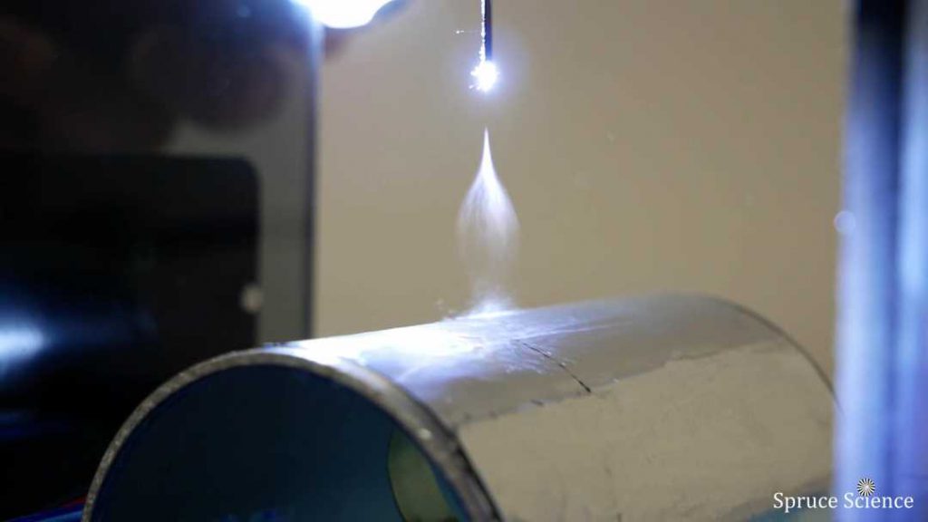
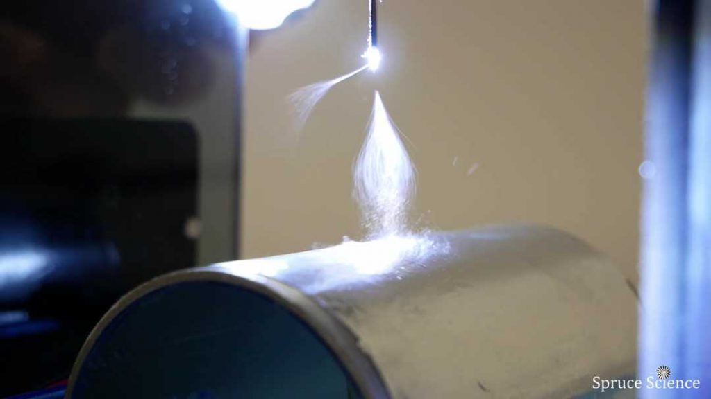
Electrospinning Process Demonstration
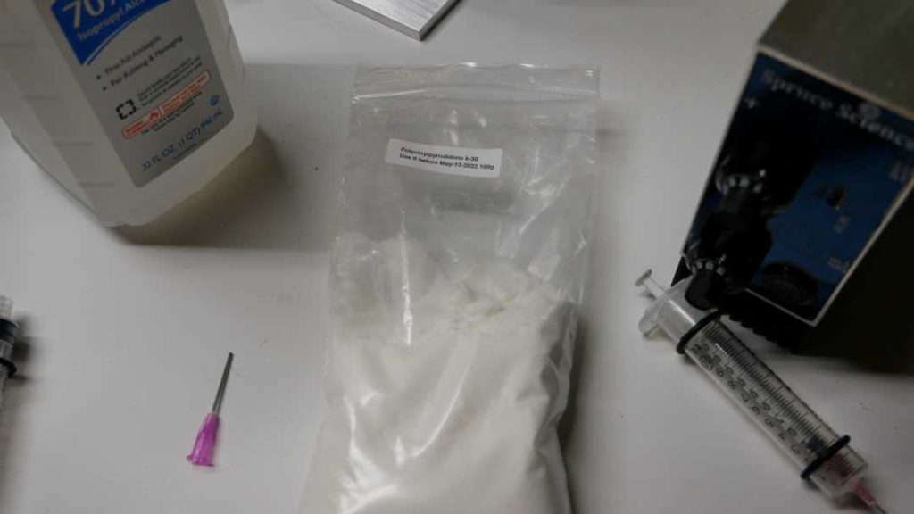
In the electrospinning process, the polymer is suspended in isopropyl alcohol inside of a syringe needle. The adjustable high voltage power supply is used to generate electrically charged fiber threads and it simultaneously establish a potential gradient between the needle tip and spinning drum collector. Under the intense electric field, these nano fibers are electrostatically elongated and collected.
1. To start the electrospinning process, begin by preparing the sample. In this demonstration, polyvinylpyrrolidone (PVP) is used for electrospinning. It is mixed together with alcohol then the mixture is loaded into the 10cc syringe. The syringe pump is then used to slowly deliver the PVP solution to the tip of the needle at a constant rate so that high voltage can be applied for electrospinning fibers.
2. Depositing the electrospun fibers on an aluminum foil works well because it is easier to gather samples with different parameters that you can go back to analyze later. This will help you fine tune the parameters for the electrospinning process.
3. We are using double sided tape to hold the aluminum foil in place. Wrap the foil around the drum collector and try to keep it tight and cut off the excess foil.
4. After the metal foil wrapping is complete, put the drum collector back in place.
5. From the control panel, set the syringe pump flow rate and collector speed. After that, turn on the motors.
6. On the high voltage power supply, adjust the current setting to the smallest output value that will work for your setup. In this particular demonstration, electorspinning did not require any current output so the current limit was kept below 0.1 mA. This will limit the current output in case there’s a short.
7. Next, set the high voltage using the dial indicator.
8. When everything is in place, turn-on the high voltage output.
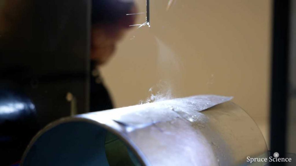
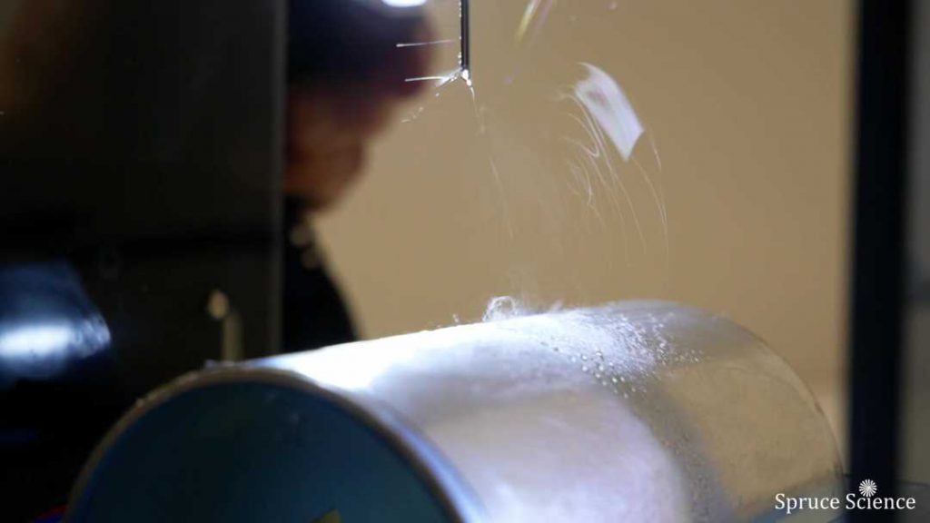
9. Observe the electrospinning action and adjust the high voltage value, collector speed and pump flow rate to get the desired result. Tuning parameters is an important part of the electrospinning process.
Summary
Electrospinning machine is the special equipment that you use to produce and collect the nano-scale fibers.
Electrospinning is performed using a syringe pump, a collector and an adjustable high voltage power supply.
Varying nanofiber materials have been successfully electrospun. There are continuing research and development efforts for different applications such as textile, filtration, protective clothing, battery separators, tissue engineering and drug delivery.
In general, primary parameters that affect the final structure of the electrospun nanofibers are the sample viscosity, dielectric constant, surface tension of the solution, solution feed rate, and high voltage applied to the polymer solution between the syringe needle and collector. The interplay of these parameters determine the constituting fiber diameter and morphology.
Electrospinning is a fascinating fabrication technique. With a small benchtop setup like the one you’ve seen, you can do a lot of interesting research and development.
Electrospinning Process Video Demonstration